First of all, we need to point out that the main task of all fume hoods is to safely evacuate the acid vapors released during the tests. Apart from the standard Fume Hoods, the other types also have the same function, only the physical structure is different.

Standard Fume Hoods: Standard Fume Hoods are fume hoods manufactured and certified according to TS EN 14175 quality Standards, generally used in Chemistry, Physics and Biology Laboratories. We have said before that it is designed in different sizes. Now let's see my system's Physical, Mechanical and Electrical features and functions in detail.

Physical Features
The body block, side panels, front panels, rear panel, gas discharge panel, lighting panel, service columns and mobile lower cabinets of the device are completely made of Galvanized sheet in various thicknesses. All surfaces are painted with 60 micron thick anti-acid Epoxy paint, which is highly resistant to acid environment, and baked at 200 degrees. Again, on the parts of the side panels that touch the ground, there are screw feet made of hard PVC for balancing the device and protecting against corrosion. There is also a second air panel inside the rear panel that facilitates the evacuation of heavy gases.


At the top of the device is the upper front panel, which connects the two side panels from the top. With this panel, a reservoir is formed in the upper part of the system. In this chamber, there is a Lighting panel on which the Lighting fixture can be mounted. At the bottom of the lighting panel, there is also a tempered and sandblasted glass protector so that the luminary and the gases in the inner chamber do not come into direct contact. The discharge pipe connection mouth with a diameter of 200 mm, which will bring the gases that will be released inside with the discharge pipes, is also designed as a monolith together with this panel.

The part to which the work surface will be connected is designed to be at a height of 900 mm from the ground together with the table. In some special designs, this height can be made as 750 and 600 mm. In this case, the height of the lower cabinet decreases, the height of the inner working chamber and the window opening distance increase. Optionally, it is made in sports systems where glass tubes can be attached.

The upper chamber is also designed to house the central units of the Alarm system and Optional Automatic Window Control systems.

At the bottom of the bench surface is the Center service panel, which connects the two side panels. This panel is designed in such a way that the main fuse box, the digital inverter controlling the fan system and the gas pressure reducing regulators are mounted.

There are two vertical service columns in front of the two side panels of the device. One of the service columns is designed in such a way that the external control valves that control the electrical lines and armatures, and the other gas lines and the nozzles in the interior can be mounted safely. A space has been created at the bottom of the Middle Panel to accommodate either standard mobile type or ventilated type lower cabinets. They can be deployed in this section in desired types and features. In ventilated type lower cabinets, air can be connected to the upper exhaust discharge pipe.

Mechanical Properties
The Mechanical Properties of Fume Hoods can be defined as the Bench Surfaces to be used, Sink and Water systems, Gas Systems and Windshield system.

Surfaces alternatives vary, just like in laboratory benches, but since it will be exposed to the most acids and chemicals in terms of the area to be used, its normal thickness is 26 mm as a standard, 33 mm thick with water-stops as one pieceDIN EN 12916 We prefer the Stoneware (Imported Industrial Ceramic) counter surface in our standards. In addition to this, preferably Epoxy Resin or Trespa Top Lab Plus bench surfaces can also be used.

The Cup Sink used on Stoneware and Epoxy Resin Surfaces are also of the same material. On the Trespa Surface, Polypropy – len Cup Sink is used.

AlthoughCold Water is generally used in fume hoods, in some cases it is used in hot and coldMix type faucets. In this case, the size of the sink attached to the counter surface also increases. Optionally, Decriminalized water taps can also be used.

A combustible gas tap is used as standard in the fume hood. This can usually be LPG, but in some cases it can also be Natural Gas. Apart from that, optionally Acetylene, Propane, Butane etc. Type gases can be added optionally.

It may be required to be used in Pressure Reducing Regulators for some flammable gases to be used in experiments and tests. It can be added optionally and optionally.

In some cases, users may request Technical Gas instead of Combustible gas. In this case, a technical gas tap can be given instead of flammable gas. These can usually be Compressed air or Nitrogen. If desired, both flammable and technical gases can be deployed together. Pressure reducing regulators are used when low pressure is required in technical gases. According to the characteristics of the gases to be used in the installations, Copper or Stainless steel piping and fittings are used.


The windshield is directly related to the air discharge performance of our Fume Hood. Performance tests to be made are made according to the condition of this glass. The glass of our Fume Hood must be closed at the time of operation. Necessary interventions should only be made at the time of operation and closed again. Otherwise, we will evacuate the air that we have conditioned by paying money in our laboratory area. Even when the window is closed, there is sufficient opening at the bottom to ensure air circulation. In addition, the glass is kept at a 50 cm opening during the Air Velocity Performance Test. At this distance, the air speed of our furnace should be minimum 300 and maximum 500 m/s. For this, appropriate Ventilator must be selected and Exhaust Piping must be done. The fan should be selected according to the pipe distance between the place where the fan will be connected and the device, and its capacity should be minimum 1200 m3/h.

The Windshield System is a Safety Glass System that is located in the front of the Fume Hood and can move up and down mechanically.

It can be preferred as Laminated or Tampered according to the Characteristics of the Laboratory to be used. Laminated glass is a glass system that is resistant to explosion and impact, made by placing a transparent film layer in the middle of two separate glasses. It does not break apart in possible breaks and does not pose a danger to users. Tempered glass is high temperature resistant glass. Their total thickness is 6 mm.

In standard fume hoods, the up and down movement of the glass is done manually and manually. The weight of the glass is equal with the weight system mounted on the side blocks of the fume cupboards and working with pulleys and ropes. It moves up / down easily with a little force that you apply with your hand. As soon as you let go of your hand, it stays where you left it.

Optionally automatic glass control system can be made. In this case, the window can be operated manually, or it can be opened and closed automatically with the hand and foot buttons. In the system, which works with a completely electronic circuit, the window closes automatically when you are not working with the fume hood.

At the moment of closing, when your hand or any object comes directly in front of the glass, it automatically stops and moves up again. In this way, possible accidents are prevented. The shutdown time is usually programmed as 20 seconds. However, this period can be extended or shortened upon request. Thanks to the sensor located on the upper front panel, the window does not close until you leave.

Air Flow Alarm and VAV Control System is the most important element used in the realization of the Air Flow Rate Test procedure requested by the TS EN 14175 Quality Standard. Because the most important part of this test is to be able to program which data we need to get from the system, and to make the data we have programmed to be viewed on the device visually and censorial.

Air Flow Alarm and VAV Control unit consists of a Central unit with a fully electronic circuit and a Front control panel. It takes the Air Flow Rate data from the Exhaust pipe outlet on the top of our device. After passing the received data through the central unit, it warns visually in normal situations and both visually and audibly in abnormal situations on the front control panel.

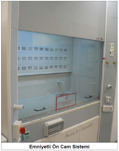
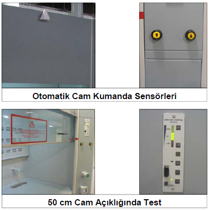
After the installation of the system to the device is completed, the minimum and maximum air flow values are entered and programmed from the Service entrance on the Front Panel. As we mentioned before, these values should be between 300 and 500 m/s at 50 cm glass opening. In some special cases, data values can be increased or decreased.

When our device is in normal operation, the warning light (middle) on the Front Control Panel lights up in Green. This indicates that the device is operating under normal conditions and at full performance.

If the warning light (Above) on the Front Control Panel is lit in Orange, it means that the air flow rate is over 500 m/s and there is unnecessary high performance air evacuation. It is not a danger signal, but you are throwing your conditioned air into the atmosphere unnecessarily. In this case, we need to reduce the speed of the fan from the Fan Control (Inverter – See Electrical Specifications for detailed explanation) to normalize it.

If the warning light (Below) on the Front Control Panel is lit in Red, the air flow rate is below 300 m/s or the fan is not working. This is a danger signal and also gives an audible warning. The speed of the fan should be increased or, if there is a malfunction, it should be corrected.

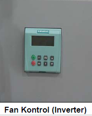
Fan Control System: (Inverter) We said that the primary function of our device is to safely evacuate the acid etc. vapors formed inside it. Therefore, the performance of our device is also directly related to the fans that should be used. Because what we need is the air suction that we will create inside. Different types of ventilators can be used in our Fume Hoods, depending on their usage characteristics. But we usually use three-phase motor Snail type Fans.

Since it is not possible to adjust the speed of the fan with normal potentiates in three-phase motors, this process is done with a Digital Inverter. The inverter converts our mono phase electricity to three phase and also allows us to adjust the rotational speed of our ventilator in Hz. In this way, we can set the normal Air Flow rate values that we need to obtain and program in the Air Flow Alarm and VAV Control unit. Our maximum speed is 50 Hz. We can adjust our speed by means of the up and down buttons on the device. When necessary, we can turn on our ventilator with the green button on the device and turn it off with the red button.

Electrical Characteristics The electrical fixtures that enable our device to work and that are used in the tests and experiments to be made form the electrical properties of the system. It consists of the following parts;

  • Main Power Cable
  • Main Safety Condition
  • Fuse Box
  • Electrical Sockets
  • Lighting Fixture
  • Keys
  • Fan Control System
  • Air Flow Control Unit
  • Automatic Glass Control Unit

Main Energy Cable It is the Mains Power Cable that will feed the whole system. A 5 x 4 (L1+L2+L3+N+PE) cable should be installed by users to the place where we will deploy our device in the laboratory. One of the 3 phases is used in the Fan Control unit, one in the electrical sockets and the other in the lighting fixtures and other systems that require electricity.

Other ends are Neutral and Grounding line. Apart from the main cable, 4 x 2.5 (L1+L2+L3+PE) Fan Start Cable should be drawn from the part where our device is located to the place where our three-phase ventilator will be deployed. After our Main Energy cable is connected to the Main Safety Condition, which will cut off the electricity of the system in case of emergency, the Fuse Box is entered.

Our fuse box is in IP 55 norms and there are 3 x 32 A main fuses and a total of 4 1 x 16 A semi-automatic fuses, one for each of the double sockets, lighting fixture, fan control and alarm system and automatic glass control system.

There is a double Grounded Socket in IP 55 norms on both sides of our device. There is 1 semi-automatic fuse in the fuse box for each double socket.

Our Daylight Lighting Fixture is in IP 65 norms. The Switch controlling the armature is in IP 55 norms and has a semi-automatic fuse in the fuse box.

The function of the Inverter that controls the fan is explained in the Fan Control System section. It consists of Central Unit and Front Control Panel. It is protected by a semi-automatic fuse in the fuse box. The Air Flow Alarm and VAV Control system and the Automatic Window Control System are also separately composed of the Central unit and Front Control panels. These two systems, consisting entirely of electronic circuits, are also protected by a semi-automatic fuse in the fuse box.

Fume Hood Base Cabinets

These are the cabinets located at the bottom of our Fume Hoods and designed to store various chemical materials used in our daily operations. Base cabinet sizes are also different according to the width of our fume hoods. We have two types of Fume Hood Base cabinets according to usage characteristics.

  • Standard Mobile Base Cabinets
  • Ventilated Base Cabinets

Standard Mobile Base Cabinets are made of galvanized sheet metal and all surfaces are painted with 60 micron thick anti-acid Epoxy paint, which is highly resistant to acid environment, and baked at 200 degrees. The doors are double-walled and have an adjustable shelf inside. Thanks to the roulettes at the bottom of our cabinets, it can move mobile, when necessary, it can be removed from its chamber and the installations at the back can be intervened.

Ventilated Base Cabinets are also completely manufactured from Galvanized sheet metal and painted with anti-acid epoxy paint and baked. Ventilated type cabinets are double-walled and there is a space between the two panels to create airflow.

Air suction is provided inside the cabinet by means of air suction vents on the base part and the lower panel. From the rear panel, there is a discharge outlet that will enable the connection of the fume hood to the Exhaust discharge pipe with the duct system. It is mainly used in chemical materials. Ventilated lower cabinets and the associated rear discharge channel are optional and made optionally.

en_GBEnglish